Gears -G Force
G-Force Performance Gears
Details:
- Stock Prowler has a 31 tooth (drive) and 34 tooth (driven) gear set. This is a 1.09:1 ratio
- G-Force performance gears have a 39 tooth (drive) and 28 tooth (driven). This is a 1.4:1 ratio
- Net effect is a final drive ratio which is 27 % higher than factory.
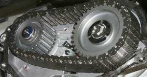
- G-Force performance gears are 1-3/4 ” wide with a single OEM chain.
- Shift points will be at a 27 % lower speed with no change in engine rpm.
- Engine rpm at any given speed will be 27 % higher with G-Force gears installed.
ie at 50mph engine rpm of 1475 will be become 1875 rpm with the gears installed. - Installation instructions and electronic speedometer adapter documentation included
Installation Instructions.
Ratio Change: example when stock gears are 31 & 34 teeth
39/28*31/34 = 1.27 => 27% gear reduction
=> ERA adapter is set at 1/1.27 = .787 nearest => .785
Parts List:
(1) Large gear – 39 tooth – transfer sprocket
(1) Small gear – 28 tooth – output sprocket
(1) Chain
(1) Electronic Ratio Adapter
(2) Quick snap connectors
(2) Crimp connectors
(1) Electronic Ratio adapter Installation Instructions
You will also require a small amount of RTV Silicone to seal the chain cover and 2 qts of transmission fluid. See your owners manual or use ATF+4 ( 1997 -1999 models used ATF+3. ATF+4 can be added to ATF+3 )
Gear Installation.
The gears are located at the back of the transmission behind the oil cooler. They are directly beneath the rear transmission cover.
1) Block up rear of car or place on a hoist. Ensure that car cannot roll.
2) Remove oil cooler. Loosen the 2 nuts(13mm) on bottom of oil cooler mounting bracket. These do not have to be removed. Remove 2 nuts(13mm) holding top of oil cooler mounting bracket to frame. Disconnect electrical wire (squeeze tab) from oil cooler fan. Free oil cooler assembly by sliding it forward off bolts and swing to the left ( driver) side. Suggest to secure it to left exhaust pipe for support.
3) Remove rear transmission mount. Remove nut(18mm) from main mount bolt. Do not remove bolt. Lift transmission slightly until bolt is free. This can be accomplished by placing a wooden shim (approx 1⅛”) between the cross member and oil pan. Be sure to place the wedge at the edges of the pan as there is little strength /support in the middle of the pan. Remove main rear mount bolt. Remove 4 bolts(15mm) which mold the mount to the transmission cover.
4) Remove drive chain cover. Remove bolt (15mm) holding ground strap to cover. Remove all chain cover bolts (13mm). Ensure all are removed (12). Place pan under cover to collect transmission fluid – approx 2 qts. Slowly pry cover from transmission. Start at each bottom corner. The sealant does hold tight but will break loose with continuous pressure.
5) Remove gears. Each gear is held in place with a snap ring and wave washer. Remove the snap ring. This can be done with a flat screw driver starting at one end and carefully working around the ring. Do NOT stretch the snap ring. Remove the spring washer. Slide both gears and chain, as one assembly, from the shafts. Ensure that the output sprocket spacer remains on the output (left, driver side) shaft. Note that the “hollow” side of the gears cover the base of the shafts.
Mark or tag the gears and chains so that they can be re-installed exactly the same way. The chains will have already worn into the gears and so should only be re-installed in the exact same configuration. ie – inside vs outside chain and mark the “rear” side of each chain.
6) Clean the surfaces of the chain cover and also transmission housing.
7) Install gears. Again as a set, slide both gears and chain on to the transmission shafts. Place the small gear to the left, (driver side) and ensure that the “hollow side of the gear goes over the base of the shafts. Replace the wave washers and snap rings. Double check that the snap ring is securely installed. By hand, push and pull on the gears to ensure that the snap rings are set.
8) Install chain cover. Put a ⅛” bead of silicone on the chain cover. Do not use excessive silicone as it will just squeeze out. Replace cover and bolts. Replace ground strap.
9) Replace transmission mount & main mount bolt & nut.
10) Replace oil cooler and reconnect fan electrical connector.
11) Remove support from between oil pan and cross member.
12) Top up transmission oil. Check in Park with engine idling. See Owners Manual for details. Start by adding only one quart and then measuring. Do not overfill.
Electronic Ratio Adapter Installation.
The easiest location to install the ERA is in the trunk, right next to the transmission control module (TCM). If you wish to locate the ERA below the insulation mat, feed the wires through the mat before making connections to TCM.
1) Ensure that the ignition is turned off and disconnect the battery. This is for safety and that the TCM will “re-learn” with the new gears.
2) Remove the blank plastic cover of the cable connector on the TCM to expose all the wires. There are two snaps on each side. You do not have to disconnect the connector from the TCM.
3) Locate 3 wires – pin 58 , white with orange stripe , speed sensor (VSS)
– pin 57 , black with red stripe, ground
– pin 11 , red with white strip, switched +12 volts
Pin 57
Pin 58
Wires
Pin 11
4) With quick snap connector, splice the Red (+12) of the ERA to red/white (switched +12) of TCM.
With quick snap connector, splice the Black (ground) of ERA to black/red (ground) of TCM.
Cut the speed sensor wire (white/orange) approx in the middle of the connector. Bare ¼” of each wire end. With crimp connectors connect the Blue(signal out) wire of the ERA to end of wire that comes from wire harness. Connect the White (signal in) wire of ERA to end of wire that goes to TCM.
NOTE: When splicing wires, remember to position connectors so that black plastic cover can be replaced.
5) Replace the black cover
6) Connect battery.
The ERA has been pre-set to the proper settings for the G-Force Performance gears. The manual describes the various settings in detail. Select a three wire VSS system and a ratio of .785 ( Dip4=> 0101 Dip12=> 001101100111 where 0=OFF 1=ON )